
![]()
![]()
![]()
![]()
![]()
![]()
![]()
![]()
![]()
![]()
![]()
![]()
![]()
![]()
![]()
![]()
![]()
![]()
![]()
![]()
![]()
![]()
![]()
![]()
N3OC Ring Rotor Page
Introduction
This page will have some info that I am sharing on supporting Tic-Gen Tic-ring 1022 ring rotors. Most of the information I have matches the rotors I have, which I believe are 1022C. There are many variations of these, so what you have might not match completely.
These rotators are no longer made or supported. So if you have one of these, you are pretty much on your own keeping it running. It's hard to believe these things are 30 years old now! Time really flies!
The good news is they use a lot of off-the-shelf (COTS) parts, many of which are still available.
Here I will list the issues I have had over the years and the solutions to those problems. If you would like to contribute any information to this page, please look up my email address on qrz.com and shoot me an email.
Brian N3OC
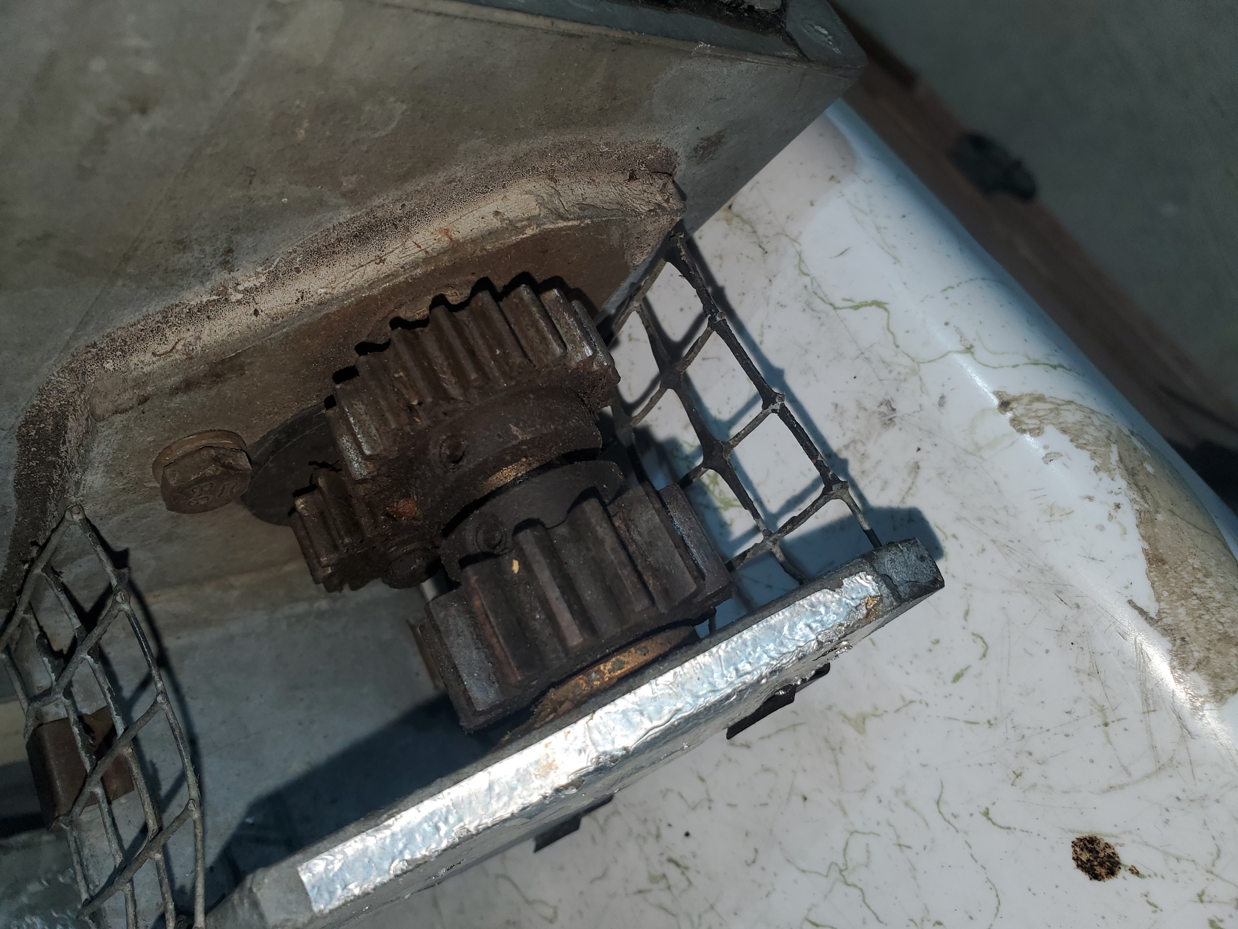
Motor Issues
There are many versions of motors that were used in the various revision levels of the Tic Ringrotor®. Some are easier to repair than others. I have even seen one that was impossible to repair as it appeared to be welded up inside it's box.
The motors seem to have been offered in silver galvanized housings and black painted housings. The ones I have are the silver galvanized housings and most of the info I have is on those C versions.
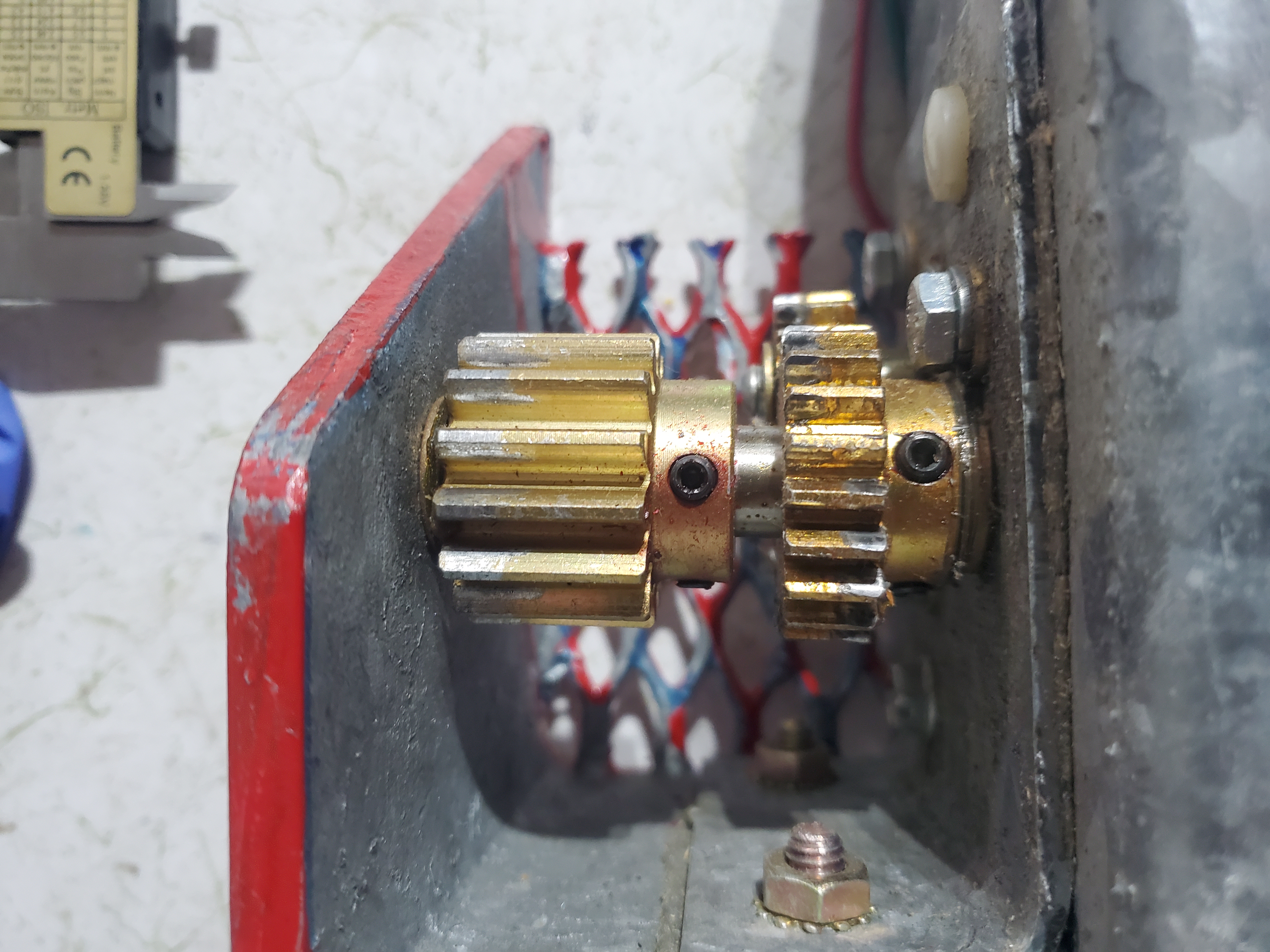
The motor appears to be a SWF 402.743 windshield wiper motor and gearbox, and are available at auto supply stores and eBay.
Info is needed on the white plastic gear for the indicator pot, and this gear can become damaged if the rotor over travels.
The indicator pots do go bad. They can burn out from RF or surges, and they can become physically damaged from over-travel.
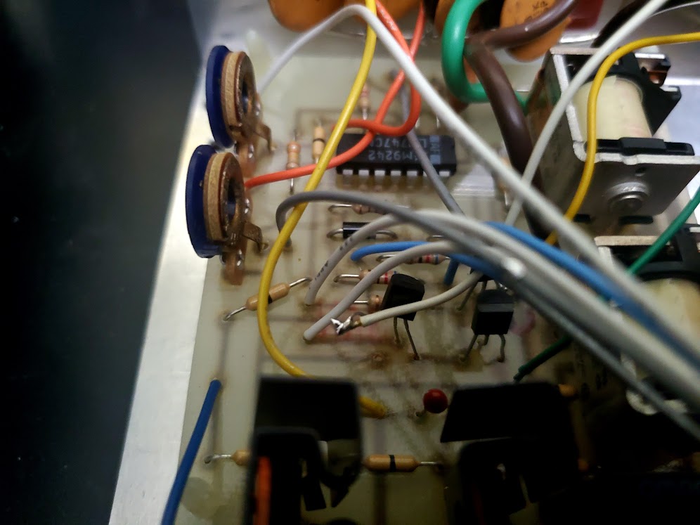
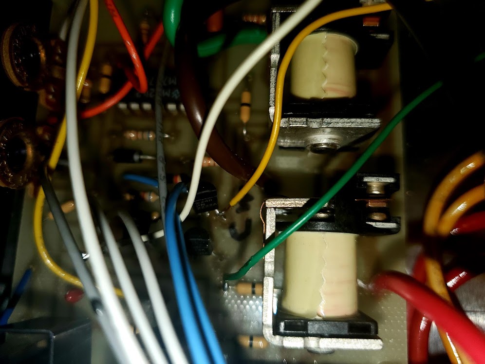
Control Box Issues
Control box issues generally involve surges on the cables, and U1 is fairly easy to blow. If you do blow one, install a socket to make its replacement easier next time.
The start pushbutton also can become flaky and needs replacing.
The indicator lights can be upgraded to LED by taping a strip of white 12v LEDs to the top of the meter and connecting them to V+ at the output of VR1.
Motor Additional Surge Protection
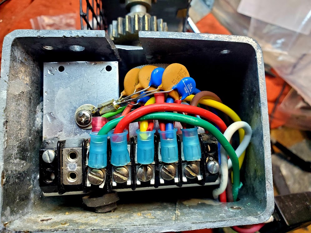
The motors have surge protection for the motors, but not the indicator pot. In addition, if you have an unlucky resonant length of rotor cable you can induce enough RF with high power to burn out the pot. You should add an MOV and a .01uf cap to ground across all three of the pot terminals inside the motor box.
RS-232 Control with EA4TX Box
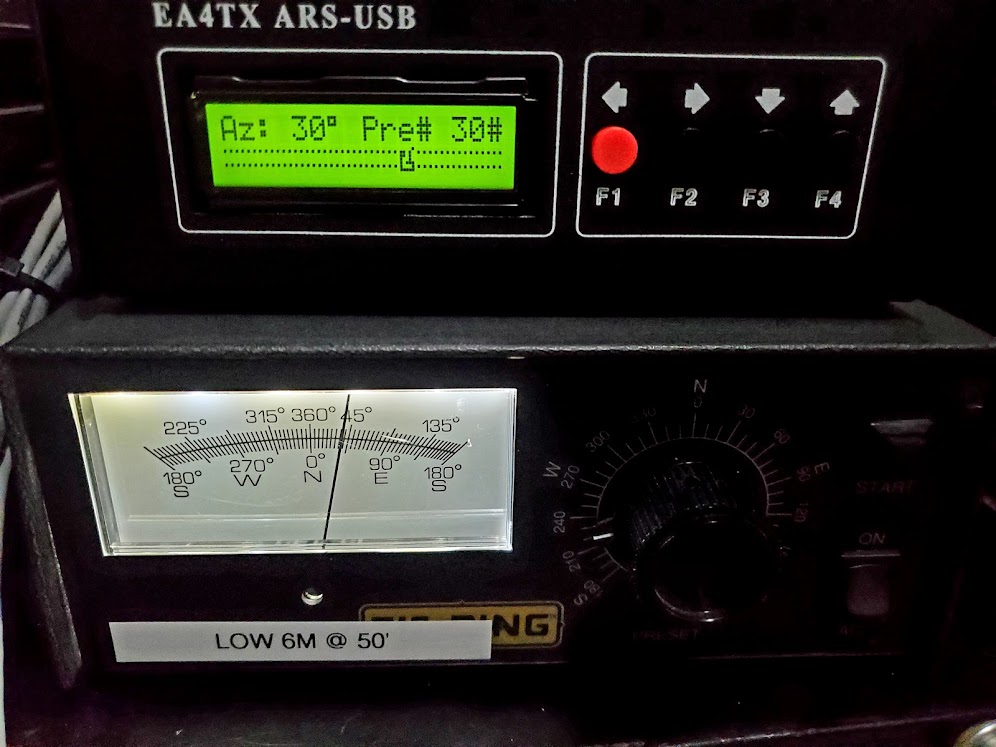
The analog point-and-shoot controller can be made USB remote-capable by paralleling it with an EA4TX azimuth-only controller box.
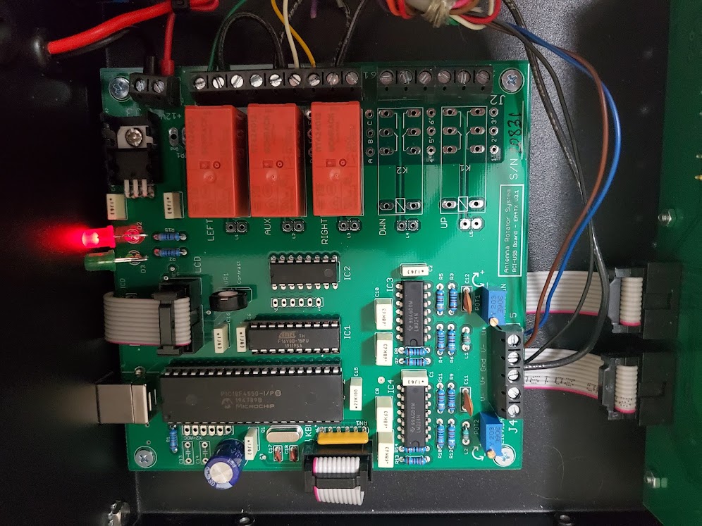
This requires some minor modifications to the tic-ring analog controller for this to work. Triac TR1 provides the latch ground when the start button is pressed in the tic-ring analog controller box. This has to be lifted from ground, and run through the AUX relay (K4) normally closed (NC) contact. This reconnects the triac when the remote USB box is not moving the rotor so that the original controller can still be used.
Then the EA4TX box is simply paralleled with the existing controller box to energize K1 to move the rotor in one direction, and energize K2 to move it in the other direction, disconnecting the triac during the time the EA4TX box is moving the rotor to prevent it from latching.
Once the EA4TX box cycle completes, the triac is reconnected by the NC contact of the AUX relay to allow the original control box to be used.
This works quite well with software remote control as the EA4TX box emulates a Yaesu rotor, so it can be used with N1MM+ rotor control or other rotor control programs.
The only downside is if you remove the EA4TX box for some reason, you loose the normally closed loop for the triac ground. I set up mine with a jumper on the terminal strip in the back so if I take off the EA4TX box, I can install the jumper on two terminals to reconnect it without having to go inside the box and solder it back on.
The rough procedure for this modification is:
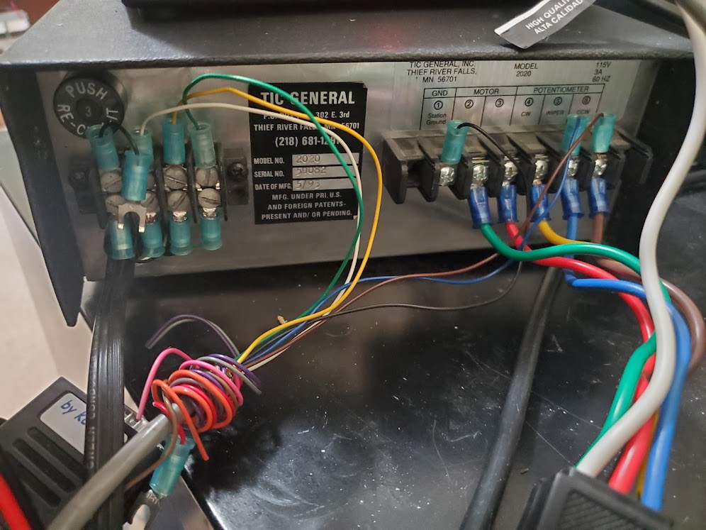
Install an additional 4-position terminal strip on the rear of the tic-ring control box. This will be used for CW motor control, CCW motor control, and the NC loop between ground and triac TR1.
Carefully drill a hole in the rear of the tic-ring control box to the right of where the line cord enters, and grommet it. This hole will be used to pass the wires through for the CW and CCW relay control wires, as well as the normally closed loop for the triac latch.
Connect a short piece of black wire to ground inside the control box, run it out through the grommet and connect it to bottom row position 1 of the terminal strip you added.
Unsolder the ground side of triac TR1 inside the box, and connect the unsoldered lead to a piece of white wire and run out the rear of the box to bottom row position 2 of the terminal strip.
Make a short 1" black jumper wire with split ring crimp lugs on each end, and connect one end to the top row position 1 of the terminal strip (ground) and leave the other end unhooked. It would be connected to top row position 2 if you ever remove the EA4TX box to reconnect the triac ground.
Connect a piece of yellow wire from the bottom row position 3 of the terminal strip, though the grommet to the inside of the box and solder it to the base of K1 on the side it connects to the collector of Q2.
Connect a piece of green wire from the bottom row position 4 of the terminal strip, though the grommet to the inside of the box and solder it to the base of K2 on the side it connects to the collector of Q1.
If you want, you can temporarily connect the jumper from terminal strip position 1 and 2 and test that your control box works normally without the EA4TX box and that nothing has gone wrong so far, then pull the jumper back off the top row pin 2 of the terminal strip and proceed further.
Connect a cable for motor control between the EA4TX box and the tic-ring controller box terminal strips as follows: J1-2, J1-5 and J1-8 of the EA4TX box all get a black wire (they are grounds) and connect all three to a single black wire in the cable and connect the tig-ring terminal strip, position 1 (system ground). Connect J1-3 with a yellow wire to position 3 of the terminal strip you added. Connect J1-4 with a white wire to position 2 of the terminal strip you added. Connect J1-9 with a green wire to position 4 of the terminal strip you added. Now connect the indicator pot as follows: Connect J4-5 with a blue wire to tic-ring original terminal strip position 5 (leave your rotor cable connected too, this goes across the existing wire so the EA4TX box can "see" the indicator pot too). Connect J4-4 with a brown wire to tic-ring original terminal strip position 6. Connect J4-3 (ground) with a black wire to the same black wires connected to J1-2, J1-5 and J1-8.
Follow the calibration procedures in the EA4TX manual in the Azimuth Input Adjustment section. You might want to use the ARSVCOM software calibration procedure. In general, you want to move the antenna to the full CW position using the tic-ring control box and then put a voltmeter at test point X2-1 in the EA4TX box and adjust POT1 until the voltmeter reads 5.0 vdc. This should be enough to get you pretty close.
Hover your mouse over these pictures for an explanation:
Motor Gear Pictures
Replacement Parts
Here is some information and links to available replacement parts:
Hot-linked parts list with all the below parts plus some gear specs (work in progress)
Replacement potentiometer, Mouser
Replacement potentiometer, DX Engineering
Replacement Motor (SWF 402.743 windshield wiper motor and drive gears), EBay
Analog controller U1 747 dual op amp, Mouser
Socket for U1 (always install a socket if you have to change U1), Mouser
Triac TR1 Q201E3, Mouser - this is a problem, obsolete, suggest trying Q401E3
Transistor 2N2907 PNP Q1 Mouser
Transistor 2N2222 NPN Q2, Mouser
MOV for surge protection, Mouser
.01uf 1kv cap for surge protection, Mouser
Plastic ring support roller wheels - drill out 2" furniture roller wheel (LOL)
Indicator pot plastic gear - 1022C (72 teeth, verified)
Indicator pot plastic gear - 1032C (55 teeth, not verified)
Manuals and other Links
Here are some manuals and external links with further information:
Original Tic-Gen web site with some information and downloads
Tic General 1022 Ringrotor® manual (working on scanning this end, not available yet)
Tic General 1032C Ringrotor® manual
Tic General 2020 controller manual
Tic General 2100B controller manual
Tension bearing update (removes tension spring and replace with fixed adjustment bolt)
Ringrotor® accessories (that were once available)
Modified 2020 controller schematic for EA4TX box
73!
Brian N3OC
Last updated 12/09/2024