![]()
![]()
![]()
![]()
![]()
![]()
![]()
![]()
![]()
![]()
![]()
![]()
![]()
![]()
![]()
![]()
![]()
![]()
![]()
![]()
![]()
![]()
![]()
![]()
80 Meter Wire Beam
For the last few years, I have been the 80 meter CW op at W3LPL for the CQWW and ARRL DX contests. After operating 80 meters at Frank's place, just about anything else is a disappointment. So I really wanted to find something that would work well at my QTH, given the limitations of my "short" 100 foot towers.
I considered many alternatives, but the thought of a wire beam on a rope boom strung between the two towers continued to intrigue me. My towers are in-line towards Europe (NE) and VK/ZL (SW). We have an antenna like this at V26B, at a lesser height, and it performs well. So I used Eznec 3.0 to model several different designs and ideas until I came up with something I liked.
The goal was to be simple, and effective. In the end I decided I really did not want any phasing lines, networks, or relays. Not that these techniques don't work, I just tend to be an instant gratification type of person. I wanted to put something up that just worked and was also reliable. So after lots of time modeling on the computer, I decided to try an inverted-vee wire beam, with a common reflector in the middle, and a driven element on each end that would make the antenna switchable from NE to SW just by switching feedlines. I also wanted to be able to use the antenna on both SSB (3800) and CW (3500) so I put a lug on the end of each element tip to facilitate attaching an extension link for CW contests.
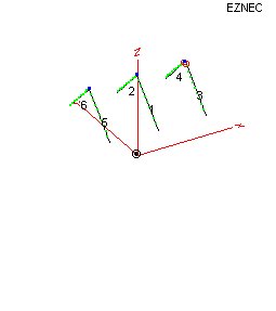 Here
is the Eznec picture of the antenna. Wire #1 and #2 are the common
parasitic reflector in the middle, wire #3 and #4 are the NE driven element, and
wire #5 and #6 are the SW driven element. All three elements are hung on a
3/8" rope boom strung between the two towers at 100 feet (30 meters).
Here
is the Eznec picture of the antenna. Wire #1 and #2 are the common
parasitic reflector in the middle, wire #3 and #4 are the NE driven element, and
wire #5 and #6 are the SW driven element. All three elements are hung on a
3/8" rope boom strung between the two towers at 100 feet (30 meters).
The driven elements have feedlines taped to the rope boom that go to each end of the boom, and attach to a piece of 1/2" hard line at the top of each tower. I can then switch directions just by switching feedlines from inside the shack, with no moving parts or networks to deal with outside.
The spacing between the elements is 60 feet (18 meters). A more traditional closer spacing produces a slightly better front to back ratio, but it also significantly lowers the drive impedance of the driven elements, and I just didn't want to mess with any matching networks. So I moved the driven elements around on the model until moving them closer to the reflector until the model indicated the feed impedance would be around 50 ohms.
The element lengths are as follows. The driven elements are 62 feet (18.9 meters) long for SSB, or 67 feet 4 inches (20.52 meters) long for CW on each side of the feedpoint. The reflector is 63 feet 6 inches (19.36 meters) long for SSB, or 68 feet 11 inches (21 meters) long for CW on each side of the center point.
It is interesting to note that using the dimensions for SSB (3.8mhz) the reflector becomes a director when you use the antenna on CW, and therefore it works backwards, with a fairly high SWR on the driven elements. So it is possible to use the antenna on CW with the SSB dimensions, it will just work backwards and require a tuner on the driven elements. I first noticed this on the model, and when I tried it on the actual antenna once again the model was correct. I suppose it might be possible to cut the driven elements for mid-band, 3.675mhz and operate with a 2:1 SWR on 3.8 and 3.5, using the parasitic element as a reflector on 3.8 and a director on 3.5
There are a lot of ways to design wire yagis, but what I like about this one is it's simplicity. No networks, no relays, no moving parts at all to fail, just coax and wire.
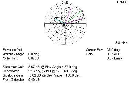
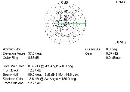
Here are the elevation and azimuth patterns that the model predicted. The combination of the low height and inverted-vee configuration resulted it a higher takeoff angle than I wanted, but there is still plenty of gain at the takeoff angles of interest. The models are showing the gain in dBi, so deduct 2.2db from the gain shown below.
So, how does it work? Well, so far, the antenna appears to really be a winner. I starting hearing Europe at 3:30pm local time (at the winter solstice), worked a long-path VK6 at 4pm, followed by a lot of Europeans immediately afterwards. All of them said the signal was very strong, and the antenna really hears well too, better than my beverage does. DK2HY called the antenna a real "band opener". Most Europeans I have worked are 59+, and the first two nights I worked G4EZT, GI0VJE, GI7THH, S52B, UT5MM, UX3IV, YZ1LT, RZ6AAB, ER4DX, LA7SL, DK2HY, DL2LZ, EA6/OE6MBG, DL8PG, DF7YT, and A45WD, all with ease. In the morning around 6am local time I worked LA6WEA who said he was running 40 watts (I was a little surprised to work Eu at 6am local, but remember it is the winter solstice, so I guess there really is no sun in Norway this time of year!). Then this morning ZK1CG told me I was 59+20 on South Cook. Wow! (In all honesty conditions were good too...)
I was really impressed that the model could be translated successfully into reality on the first cut. I was careful to use a velocity factor of .98 for the insulated wire, but other than that I used the exact dimensions I worked up in the model and it worked just fine. Click here if you want to look at the actual model file that was used.
The bad thing about this antenna is that is does not do well at all to JA, as might be expected. I will have to come up with a secondary antenna for those directions, but my first priority was to be LOUD in Europe!
73, Brian N3OC