![]()
![]()
![]()
![]()
![]()
![]()
![]()
![]()
![]()
![]()
![]()
![]()
![]()
![]()
![]()
![]()
![]()
![]()
![]()
![]()
![]()
![]()
![]()
![]()
Station Construction
Part III - The "Un-Beezer" Trench & Grounding
 The
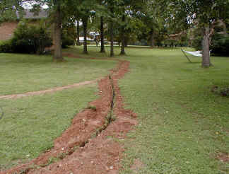
final part of the install was to dig the trench, and run the rotor cables,
stackmatch control cables, and hard lines.
The
final part of the install was to dig the trench, and run the rotor cables,
stackmatch control cables, and hard lines.
Another visit to the rental place produced a medium sized ditch witch trencher, which I trailered home.
Then K1DQV and I ran the beast from each tower to the house. Again we hit rocks, and the ditch witch was amazing that it could yank four or five inch rocks out of the trench and throw them aside.
 I
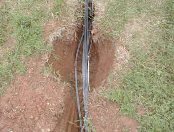
elected to directly bury the cables and not use conduit. Conduit is nice,
but it always fills up with water anyway, so all it really does is provide
physical protection to the cables.
I
elected to directly bury the cables and not use conduit. Conduit is nice,
but it always fills up with water anyway, so all it really does is provide
physical protection to the cables.
So I chose direct burial type of cables. UF Romex was used for the rotor and stackmatch control cables, and Andrew LDF Heliax was used for the feedlines.
UF Romex is a great choice for rotor cables. It is cheap, and can be directly buried. Two runs of romes provide six wires, and the motor start capacitors were relocated to the junction box at the base of the tower to avoid the need for the 7th and 8th wire. Ring rotors run on DC and have no brake, so they only need five wires. A total of 18 runs of UF romex were run to the towers, ten to the first tower, and eight to the second. Two romex runs per rotor and stackmatch, plus some spares.
 Grounding
consisted of a ring of #2AWG tinned solid wire put in the trench before the
rotor cables and feedlines.
Grounding
consisted of a ring of #2AWG tinned solid wire put in the trench before the
rotor cables and feedlines.
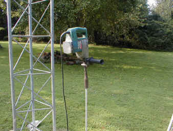
Ten ground rods were pounded in using a hammer drill with the proper attachment to pound ground rods. When the ground rods hit a rock, a sledge hammer was used to crack the rock so the hammer drill could continue it's work
All the ground rods were cadwelded to the ground wire in the trench. Galvanized ground rods were used to minimize and galvanic corrosion, copper ground rods are just a little too reactive.
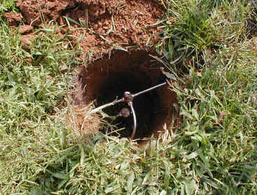
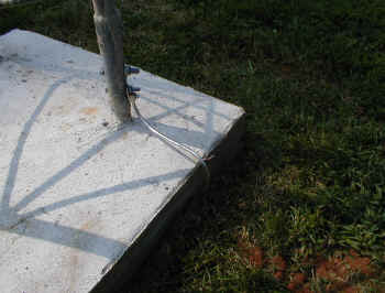 The
ground ring was attached to the tower base at two points using compression lugs
connected to the tower bolts.
The
ground ring was attached to the tower base at two points using compression lugs
connected to the tower bolts.
Do not cadweld to a tubular leg tower - there is a slight possibility the cadweld might burn through the leg.
Only compression lugs should be used with solid wire, so they can be periodically tightened if needed. Do not use crimp-on lugs with solid wire. They are fine for stranded wire.
The #2 ground wire was brought back to the house, and attached to the house ground at the panel box. That way, the entire grounding system has a chance to remain at the same potential during a lightning strike and minimize damage to the equipment. You might think that this would bring lightning in to the house from the towers, but remember it has to go by several ground rods before it gets to the house.
The ground system was measured using a commercial ground tester, and the impedance was measured at 1.5 ohms, which is a VERY good ground. You can see the impedance drop every time an additional ground was added. A single ground rod has an impedance somewhere around 30 ohms if you are lucky, so it is a must to have many ground rods tied together with a large size conductor to achieve a good ground. A good ground is usually defined as 5 ohms or less.
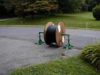 A
cable jack makes it easy to unroll the Heliax cable off of the large rolls.
A
cable jack makes it easy to unroll the Heliax cable off of the large rolls.
Tower #1 required five 450 foot runs of 1/2" LDF cable.
Tower #2 required five 280 foot runs of 1/2" LDF, and four 280 foot runs of 7/8" LDF for the higher VHF bands.
The upper connectors were put on all the cables, and Brian, N3ST went up the towers while I hoisted the cables up. He then dressed all the feedlines down the towers, and we stuffed them into the trench.
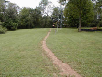 Then
the trench was filled in and the dirt tamped down. I drove the tractor up
and down the trench to compress the dirt, and was able to get all the dirt that
came out of the trench go back in.
Then
the trench was filled in and the dirt tamped down. I drove the tractor up
and down the trench to compress the dirt, and was able to get all the dirt that
came out of the trench go back in.
I planted grass seed over the trench, and within a couple weeks the lawn was completely restored, making my wife happy.
Oh, by the way, the reason I call it the "un-beezer" trench is that most guys take forever to fill in their trench, including the Beezer, Bob W2BZR. Mine was all done within a week!
The complete tower installation was done by the end of August, and the lower antennas and stack matches were done by the end of September. The 80 meter wire yagi was completed at the end of December, so all my friends and I really moved along here and constructed a pretty good station in just a couple months!
Future plans include adding 2304 and 10ghz to the VHF station (completed in May 2004), improving the 160 meter antennas, and adding a third tribander to the stack at 32 feet.
Here is a list of hams that helped construct the station: Charlie KA3IWP, Bob W9GE, Roger K1DQV, Brian N3ST, Bill N3RR, Tony K3WX. Frank W3LPL provided invaluable design assistance, and Norm W3NRS (now W4NRS) provided the tower services and crane. Maurice KA3EJJ machined the custom thrust bushings for the tower tops. Thanks to all that helped, no way I could have done this by myself. Even my wife Terry pitched in and helped me fill the trench.
CU in the pileups!
Brian, N3OC